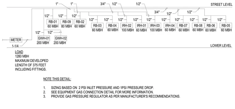
This natural gas piping schematic details the distribution layout from the building meter up to the street level with a total load of 1280 MBH and a maximum developed length of 375 feet including fittings. Pipe sizing is based on a 2 PSI inlet pressure and 1 PSI pressure drop, utilizing varied pipe diameters from 1/2 inch up to 1-1/4 inches. The system supplies multiple labeled equipment drops including water heaters GWH-01 and GWH-02 at 200 MBH each, along with various radiant heaters and boilers ranging from 60 MBH to 100 MBH. Gas pressure regulators must be provided per the manufacturer's recommendations.
LOWER LEVEL STREET LEVEL NOTE THIS DETAIL: 1. SIZING BASED ON 2 PSI INLET PRESSURE AND 1PSI PRESSURE DROP. 2. SEE EQUIPMENT GAS CONNECTION DETAIL FOR MORE INFORMATION. 3. PROVIDE GAS PRESSURE REGULATOR AS PER MANUFACTURER'S RECOMMENDATIONS. LOAD 1280 MBH MAXIMUM DEVELOPED LENGTH OF 375 FEET INCLUDING FITTINGS. 1-1/4 200 MBH 1/2" 1/2" 200 MBH 1/2" 1/2" 1/2" 1/2" 1/2" 1/2" 1/2" 1/2" 1/2" 1/2" 1/2" 1/2" 1/2" 1/2" 1/2" 3/4" 1" 1" 3/4" 1/2" 1/2" 80 MBH 100 MBH 100 MBH 60 MBH 60 MBH 60 MBH 60 MBH 60 MBH 60 MBH 60 MBH 60 MBH 60 MBH 60 MBH METER GWH-02 GWH-01 RB-01 RB-09 RB-02 RB-03 RB-04 IRH-02 IRH-01 IRH-03 IRH-04 RB-07 RB-08 RB-06 RB-05
Members view this detail in full resolution, download the CAD files (SVG, PDF), and can adapt it in the built-in CAD editor — export DXF, DWG, or PDF.
Start membership