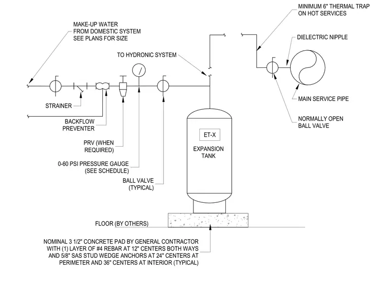
An expansion tank rests on a nominal three-and-a-half-inch concrete pad provided by the general contractor and reinforced with a single layer of number four reinforcing bars at twelve-inch centers both ways. Five-eighth-inch stud wedge anchors secure the perimeter at twenty-four-inch centers and the interior at thirty-six-inch centers. The make-up water line from the domestic system connects to the hydronic system through a strainer, backflow preventer, pressure reducing valve when required, zero to sixty psi pressure gauge, and typical ball valves. A dielectric nipple connects the main service pipe with a normally open ball valve and a minimum six-inch thermal trap on hot services.
ET-X FLOOR (BY OTHERS) MINIMUM 6" THERMAL TRAP ON HOT SERVICES MAIN SERVICE PIPE NORMALLY OPEN BALL VALVE MAKE-UP WATER FROM DOMESTIC SYSTEM SEE PLANS FOR SIZE TO HYDRONIC SYSTEM STRAINER BACKFLOW PREVENTER PRV (WHEN REQUIRED) 0-60 PSI PRESSURE GAUGE (SEE SCHEDULE) BALL VALVE (TYPICAL) NOMINAL 3 1/2" CONCRETE PAD BY GENERAL CONTRACTOR WITH (1) LAYER OF #4 REBAR AT 12" CENTERS BOTH WAYS AND 5/8" SAS STUD WEDGE ANCHORS AT 24" CENTERS AT PERIMETER AND 36" CENTERS AT INTERIOR (TYPICAL) EXPANSION TANK DIELECTRIC NIPPLE
Members view this detail in full resolution, download the CAD files (SVG, PDF), and can adapt it in the built-in CAD editor — export DXF, DWG, or PDF.
Start membership