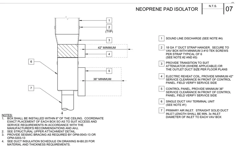
A single duct variable air volume terminal unit connects to an inlet sound line discharge and an outlet primary air inlet with a straight solid duct inlet length equal to a minimum of three times the inlet diameter. The unit is suspended using eighteen gauge one-inch duct strap hangers secured with three number ten tek screws per strap typical of six, tied to structural upper attachments and seismic bracing. An electric reheat coil is attached with a forty-two inch minimum service clearance in front of the control panel, while the main control panel maintains a thirty-six inch minimum service clearance. The box installs within six inches of the ceiling with sound line insulation and a neoprene pad isolator.
36" MINIMUM SOUND LINE DISCHARGE (SEE NOTE #4) 18 GA 1" DUCT STRAP HANGER. SECURE TO VAV BOX WITH MINIMUM 3 #10 TEK SCREWS PER STRAP TYPICAL OF 6 (SEE NOTE #2 AND #3) PROVIDE TRANSITION TO SUIT ATTENUATOR (WHERE APPLICABLE) OR THE OUTLET DUCT SIZE PER FLOOR PLANS ELECTRIC REHEAT COIL, PROVIDE MINIMUM 42" SERVICE CLEARANCE IN FRONT OF CONTROL PANEL. FIELD VERIFY SERVICE SIDE CONTROL PANEL, PROVIDE MINIMUM 36" SERVICE CLEARANCE IN FRONT OF CONTROL PANEL. FIELD VERIFY SERVICE SIDE SINGLE DUCT VAV TERMINAL UNIT (SEE NOTE #1) PRIMARY AIR INLET. STRAIGHT SOLID DUCT INLET LENGTH SHALL BE MIN. 3x INLET DIAMETER OF INLET TO EACH VAV BOX NOTES: 1. BOX SHALL BE INSTALLED WITHIN 6" OF THE CEILING. COORDINATE EXACT PLACEMENT OF EACH BOX SO AS TO SUIT ACCESS AND SERVICE REQUIREMENTS IN ACCORDANCE WITH THE MANUFACTURER'S RECOMMENDATIONS AND AHJ. 2. SEE STRUCTURAL UPPER ATTACHMENT DETAIL. 3. PROVIDE SEISMIC BRACING AS REQUIRED BY OPM-0043-13 OR OPM-0203-13 4. SEE DUCT INSULATION SCHEDULE ON DRAWING M-B0.20 FOR MATERIAL AND THICKNESS REQUIREMENTS. (TYP) 1 2 3 4 5 6 7 1 2 3 4 5 6 7 42" MINIMUM LPA N.T.S. 07 NEOPRENE PAD ISOLATOR
Members view this detail in full resolution, download the CAD files (SVG, PDF), and can adapt it in the built-in CAD editor — export DXF, DWG, or PDF.
Start membership