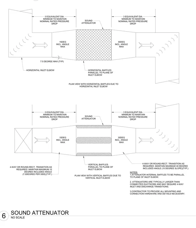
Sound attenuators connect to incoming and outgoing ductwork using four-way or round-to-rectangular transitions as required. Inlet and discharge transitions maintain a maximum fifteen degree included angle on the approach and a maximum thirty degree included angle on the exit to control pressure drop. Internal baffles align parallel to the plane of the inlet elbow, requiring horizontal baffles for horizontal elbows and vertical baffles for vertical elbows. Straight duct lengths of three equivalent diameters minimum must be maintained on both sides of the attenuator to maintain nominal rated pressure drop. The contractor provides all mounting and connection hardware and details necessary.
15DEG INCL. ANGLE MAX 30DEG INCL. ANGLE MAX 15DEG INCL. ANGLE MAX 30DEG INCL. ANGLE MAX SOUND ATTENUATOR 3 EQUIVALENT DIA. MINIMUM TO MAINTAIN NOMINAL RATED PRESSURE DROP 3 EQUIVALENT DIA. MINIMUM TO MAINTAIN NOMINAL RATED PRESSURE DROP 3 EQUIVALENT DIA. MINIMUM TO MAINTAIN NOMINAL RATED PRESSURE DROP 3 EQUIVALENT DIA. MINIMUM TO MAINTAIN NOMINAL RATED PRESSURE DROP SOUND ATTENUATOR HORIZONTAL BAFFLES PARALLEL TO PLANE OF INLET ELBOW HORIZONTAL INLET ELBOW 7.5 DEGREE MAX (TYP) PLAN VIEW WITH HORIZONTAL BAFFLES DUE TO HORIZONTAL INLET ELBOW PLAN VIEW WITH VERTICAL BAFFLES DUE TO VERTICAL INLET ELBOW VERTICAL BAFFLES PARALLEL TO PLANE OF INLET ELBOW 4-WAY OR ROUND-RECT. TRANSITION AS REQUIRED. MAINTAIN MAXIMUM 15 DEGREE INCLUDED ANGLE (7.5DEGREE PER SIDE)(TYP.) 4-WAY OR ROUND-RECT. TRANSITION AS REQUIRED. MAINTAIN MAXIMUM 30 DEGREE INCLUDED ANGLE (15 DEGREE SLOPE)(TYP.) NOTES: 1.ATTENUATOR INTERNAL BAFFLES TO BE PARALLEL TO PLANE OF INLET ELBOW. 2. ATTENUATORS ARE TYPICALLY LARGER THAN CONNECTED DUCTWORK AND MAY REQUIRE 4-WAY INLET AND DISCHARGE TRANSITIONS. 3.CONTRACTOR TO PROVIDE ALL MOUNTING AND CONNECTION HARDWARE AND DETAILS NECESSARY. NO SCALE 6 SOUND ATTENUATOR
Members view this detail in full resolution, download the CAD files (SVG, PDF), and can adapt it in the built-in CAD editor — export DXF, DWG, or PDF.
Start membership