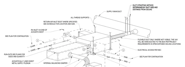
An axonometric detail shows the connection configuration for a chilled water fan terminal unit, including chilled water supply and return piping along with hot water supply and return lines. The unit features an acoustically lined sheet metal supply plenum, an internal balancing damper, and a return air inlet boot configured per project specifications. Flexible ductwork is permitted only in locations where it remains concealed from view, while open exposed ceiling locations require hard-ducted connections to the box. All-thread supports and duct strapping secure the distribution system from the overhead structure, with electrical access provided in accordance with the National Electrical Code.
HWS HWR 1 SUPPLY MAIN DUCT RETURN AIR INLET BOOT WHERE SPECIFIED. SEE SCHEDULE FOR LOCATION AND SIZE. ALL-THREAD SUPPORTS RUN-OUTS SEE PLANS FOR SIZES AND QUANTITY ACOUSTICALLY LINED SHEET METAL SUPPLY PLENUM 2 SEE PLAN FOR CONTINUATION 3 INTERNAL BALANCING DAMPER FLEXIBLE DUCT ONLY WHERE NOT VISIBLE. THE VAV WILL BE HARD-DUCTED TO THE BOX PER PROJECT REQUIREMENTS IN OPEN EXPOSED CEILING LOCATIONS. RA INLET VIA END OF ACOUSTIC BOOT SEE PLAN FOR CONTINUATION CHWS CHWR 1 2 3 ELECTRICAL ACCESS PER NEC DUCT STRAPPING METHOD DETERMINED BY DUCT SIZE AND DISTANCE FROM CEILING DUCT STRAPPING METHOD DETERMINED BY DUCT SIZE AND DISTANCE FROM CEILING
Members view this detail in full resolution, download the CAD files (SVG, PDF), and can adapt it in the built-in CAD editor — export DXF, DWG, or PDF.
Start membership