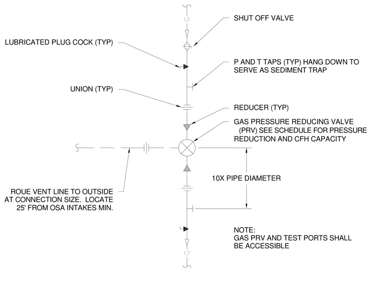
A gas pressure reducing valve assembly includes a main pressure reducing valve with pressure reduction and cubic feet per hour capacity sized per schedule. The piping layout incorporates typical shut-off valves, lubricated plug cocks, unions, and reducers. Pressure and temperature taps hang down to serve as sediment traps. A vent line routes to the outside at connection size and is located a minimum of twenty-five feet from outside air intakes. The gas pressure reducing valve and test ports maintain accessibility requirements of ten times the pipe diameter.
G G GAS PRESSURE REDUCING VALVE (PRV) SEE SCHEDULE FOR PRESSURE REDUCTION AND CFH CAPACITY REDUCER (TYP) UNION (TYP) P AND T TAPS (TYP) HANG DOWN TO SERVE AS SEDIMENT TRAP SHUT OFF VALVE LUBRICATED PLUG COCK (TYP) ROUE VENT LINE TO OUTSIDE AT CONNECTION SIZE. LOCATE 25' FROM OSA INTAKES MIN. NOTE: GAS PRV AND TEST PORTS SHALL BE ACCESSIBLE 10X PIPE DIAMETER
Members view this detail in full resolution, download the CAD files (SVG, PDF), and can adapt it in the built-in CAD editor — export DXF, DWG, or PDF.
Start membership