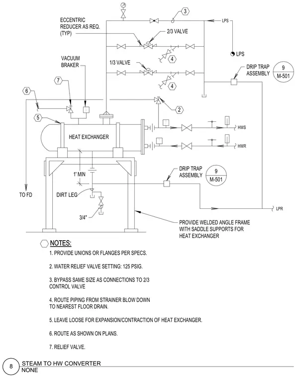
A shell-and-tube heat exchanger is mounted on a welded angle frame with saddle supports resting on the floor. High-pressure steam enters through low-pressure steam lines fitted with eccentric reducers as required, a vacuum breaker, and a water relief valve set to 125 psig. Control valves including one-third and two-third valves regulate flow with a bypass sized the same as connections. Drip trap assemblies connect to strainer blowdowns and route to the nearest floor drain or a dirt leg with a three-quarter-inch valve. Hot water supply and return lines feature thermometers, unions or flanges per specifications, and expansion provisions left loose for thermal movement.
HWS HWR LPR LPS NOTES: NOTES: T V T DIRT LEG PROVIDE WELDED ANGLE FRAME TO FD HEAT EXCHANGER 1' MIN 2 2. WATER RELIEF VALVE SETTING: 125 PSIG. 3. BYPASS SAME SIZE AS CONNECTIONS TO 2/3 CONTROL VALVE 2/3 VALVE 1/3 VALVE VACUUM BRAKER REDUCER AS REQ. (TYP) WITH SADDLE SUPPORTS FOR HEAT EXCHANGER 4 4 4. ROUTE PIPING FROM STRAINER BLOW DOWN ECCENTRIC 5 DRIP TRAP ASSEMBLY 9 M-501 TO NEAREST FLOOR DRAIN. 3 LPS 3/4" 5. LEAVE LOOSE FOR EXPANSION/CONTRACTION OF HEAT EXCHANGER. 6. ROUTE AS SHOWN ON PLANS. 7. RELIEF VALVE. 7 6 ASSEMBLY DRIP TRAP 9 M-501 1. PROVIDE UNIONS OR FLANGES PER SPECS. NONE 8 STEAM TO HW CONVERTER
Members view this detail in full resolution, download the CAD files (SVG, PDF), and can adapt it in the built-in CAD editor — export DXF, DWG, or PDF.
Start membership