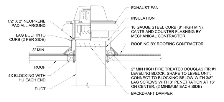
An exhaust fan mounts atop an eighteen gauge steel curb with a minimum height of eight inches, separated by a one-half inch by two-inch neoprene pad all around and secured with lag bolts at two per side. The steel curb sits on a two-inch minimum high fire-treated Douglas fir number one leveling block shaped to level the unit. This wood leveling block connects to the four-inch wood blocking below using three-eighths inch lag screws with three-inch penetration spaced at sixteen inches on center with a minimum of two per side. The four-inch blocking features hanger units at each end and surrounds the duct penetration. Roofing, cants, and counter flashing are provided by the roofing contractor, while a backdraft damper installs inside the duct throat.
3" MIN 1/2" X 2" NEOPRENE PAD ALL AROUND LAG BOLT INTO CURB (2 PER SIDE) ROOF 4X BLOCKING WITH HU EACH END DUCT EXHAUST FAN INSULATION 18 GAUGE STEEL CURB (8" HIGH MIN), CANTS AND COUNTER FLASHING BY MECHANICAL CONTRACTOR. ROOFING BY ROOFING CONTRACTOR 2" MIN HIGH FIRE TREATED DOUGLAS FIR #1 LEVELING BLOCK. SHAPE TO LEVEL UNIT. CONNECT TO BLOCKING BELOW WITH 3/8" LAG SCREWS WITH 3" PENETRATION AT 16" ON CENTER, (2 MINIMUM EACH SIDE) BACKDRAFT DAMPER
Members view this detail in full resolution, download the CAD files (SVG, PDF), and can adapt it in the built-in CAD editor — export DXF, DWG, or PDF.
Start membership