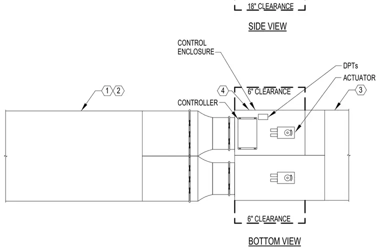
Mechanical ductwork assembly featuring a control enclosure, controller, actuator, and differential pressure transducers. The drawing indicates required maintenance clearances including eighteen inches and six inches around components. Side and bottom views show the spatial relationship and positioning of the mechanical equipment relative to the duct runs.
SIDE VIEW BOTTOM VIEW DPTs 18" CLEARANCE 6" CLEARANCE ACTUATOR 6" CLEARANCE CONTROLLER CONTROL ENCLOSURE 1 2 3 4
Members view this detail in full resolution, download the CAD files (SVG, PDF), and can adapt it in the built-in CAD editor — export DXF, DWG, or PDF.
Start membership