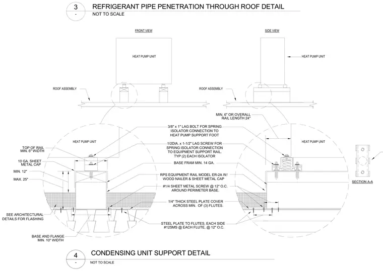
A rooftop heat pump unit is supported on an equipment rail featuring a minimum fourteen-gauge base frame with an integrated wood nailer and a sheet metal cap. A quarter-inch thick steel plate cover spans across a minimum of three metal deck flutes, secured on each side with number twelve sheet metal screws spaced at twelve inches on center. The heat pump unit mounts to the rail using three-eighths-inch by one-inch lag bolts for the spring isolator connection to the support foot, and half-inch diameter by one-and-a-half-inch lag screws for the spring isolator connection to the equipment support rail with two required per isolator. A ten-gauge sheet metal cap with a base and flange width of at least ten inches is included. Flashing requirements are coordinated with architectural details.
SECTION A-A NOT TO SCALE ROOF ASSEMBLY HEAT PUMP UNIT HEAT PUMP UNIT FRONT VIEW SIDE VIEW HEAT PUMP UNIT ROOF ASSEMBLY HEAT PUMP UNIT NOT TO SCALE - - 1/4" THICK STEEL PLATE COVER ACROSS MIN. OF (3) FLUTES. STEEL PLATE TO FLUTES, EACH SIDE #1/4 SHEET METAL SCREW @ 12" O.C. AROUND PERIMETER BASE. RPS EQUIPMENT RAIL MODEL ER-2A W/ WOOD NAILER & SHEET METAL CAP 3/8" x 1" LAG BOLT FOR SPRING ISOLATOR CONNECTION TO HEAT PUMP SUPPORT FOOT 1/2DIA. x 1-1/2" LAG SCREW FOR SPRING ISOLATOR CONNECTION TO EQUIPMENT SUPPORT RAIL. TYP (2) EACH ISOLATOR MIN. 12" MAX. 25" TOP OF RAIL 10 GA. SHEET BASE AND FLANGE MIN. 6" OR OVERALL BASE FRAM MIN. 14 GA. MIN. 10" WIDTH MIN. 6" WIDTH RAIL LENGTH 24" #12SMS @ EACH FLUTE, @ 12" O.C. SEE ARCHITECTURAL DETAILS FOR FLASHING METAL CAP 3 REFRIGERANT PIPE PENETRATION THROUGH ROOF DETAIL CONDENSING UNIT SUPPORT DETAIL 4
Members view this detail in full resolution, download the CAD files (SVG, PDF), and can adapt it in the built-in CAD editor — export DXF, DWG, or PDF.
Start membership