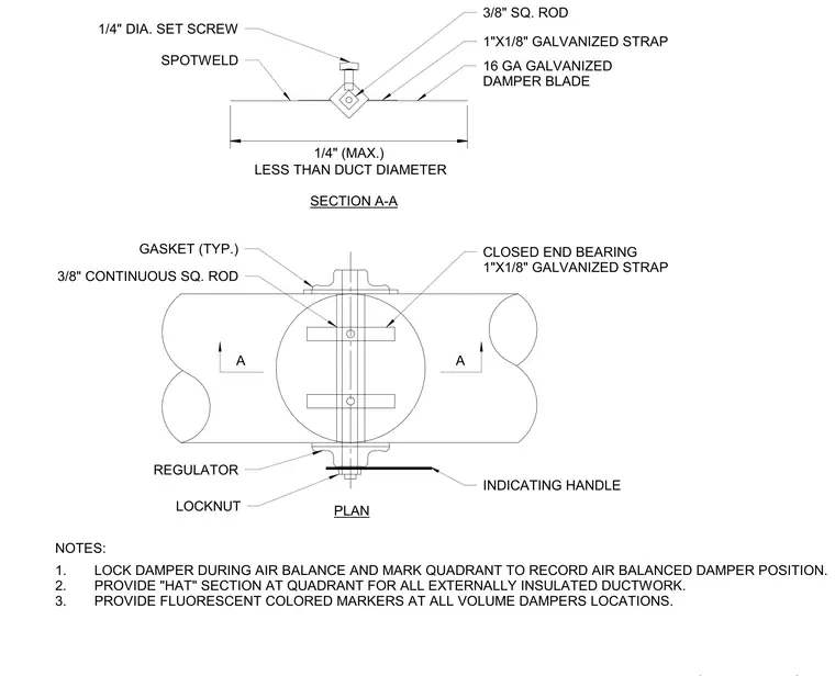
This round volume damper assembly features a 16-gauge galvanized damper blade supported by a three-eighths-inch continuous square rod spanning the duct diameter. The blade is sized one-quarter inch maximum less than the interior duct diameter. One-inch by one-eighth-inch galvanized straps secure the closed-end bearings, which are spot-welded to the duct. External controls include a regulator, locknut, and indicating handle operated by a three-eighths-inch square rod with a one-quarter-inch diameter set screw. Typical gaskets seal the penetration points where the rod exits the round ductwork.
A PLAN SECTION A-A NOTES: 1. LOCK DAMPER DURING AIR BALANCE AND MARK QUADRANT TO RECORD AIR BALANCED DAMPER POSITION. 2. PROVIDE "HAT" SECTION AT QUADRANT FOR ALL EXTERNALLY INSULATED DUCTWORK. 3. PROVIDE FLUORESCENT COLORED MARKERS AT ALL VOLUME DAMPERS LOCATIONS. 1/4" DIA. SET SCREW SPOTWELD 1"X1/8" GALVANIZED STRAP 16 GA GALVANIZED DAMPER BLADE 3/8" SQ. ROD CLOSED END BEARING 1"X1/8" GALVANIZED STRAP INDICATING HANDLE LOCKNUT REGULATOR 3/8" CONTINUOUS SQ. ROD GASKET (TYP.) A 1/4" (MAX.) LESS THAN DUCT DIAMETER
Members view this detail in full resolution, download the CAD files (SVG, PDF), and can adapt it in the built-in CAD editor — export DXF, DWG, or PDF.
Start membership