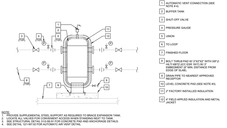
A vertical buffer tank is supported on a level concrete pad with three-eighths-inch diameter Hilti KBTZ expansion anchors embedded three inches with two-inch by two-inch by two-inch washers. The tank features factory-installed and field-applied insulation with a metal jacket, an automatic air vent connection at the top, pressure gauges, shut-off valves, and unions connected to the loop piping. A drain pipe connects to the nearest approved receptor, and supplemental steel support is provided as required to brace the expansion tank.
PRESSURE GAUGE LEVEL CONCRETE PAD (SEE NOTE #3) NOTE: 1. PROVIDE SUPPLEMENTAL STEEL SUPPORT AS REQUIRED TO BRACE EXPANSION TANK. 2. LOCATE ALL VALVES FOR CONVENIENT ACCESS WHEN STANDING NEXT TO TANK. 3. SEE STRUCTURAL DETAIL 01/2-S6.91 FOR CONCRETE PAD AND ANCHORAGE DETAILS. 4. SEE DETAIL 12/1-M7.02 FOR AUTOMATC AIR VENT DETAIL. 1 2 3 4 5 6 7 8 9 10 1 2 3 4 5 9 10 (TYP) (TYP) (TYP) 6 (TYP) AUTOMATIC VENT CONNECTION (SEE NOTE # 4) BUFFER TANK SHUT-OFF VALVE UNION TO LOOP FINISHED FLOOR BOLT THRU8 PAD W/ 2"X2"X2" WITH 3/8" ∅ HILTI KBTZ (ICC ESR 1917) W/ 3" EMBEDMENT (6" MIN. DISTANCE FROM EDGE OF SLAB). DRAIN PIPE TO NEAREST APPROVED RECEPTOR P P P P 8 7 4" FIELD APPLED INSULATION AND METAL JACKET 11 12 2" FACTORY INSTALLED INSULATION 11 12
Members view this detail in full resolution, download the CAD files (SVG, PDF), and can adapt it in the built-in CAD editor — export DXF, DWG, or PDF.
Start membership