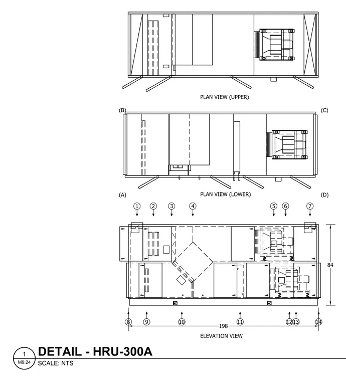
The drawing presents upper plan, lower plan, and elevation views of a heat recovery unit with an overall length of one hundred ninety-eight inches and a height of eighty-four inches. Numbered reference bubbles one through fourteen and lettered indicators A through D locate specific internal components and exterior connection points across the equipment housing. Internal airflow paths, filter banks, and fan assemblies are indicated with dashed and solid hidden lines. The unit is shown at not-to-scale proportions with standard mechanical equipment layout detailing.
Members view this detail in full resolution, download the CAD files (SVG, PDF), and can adapt it in the built-in CAD editor — export DXF, DWG, or PDF.
Start membership