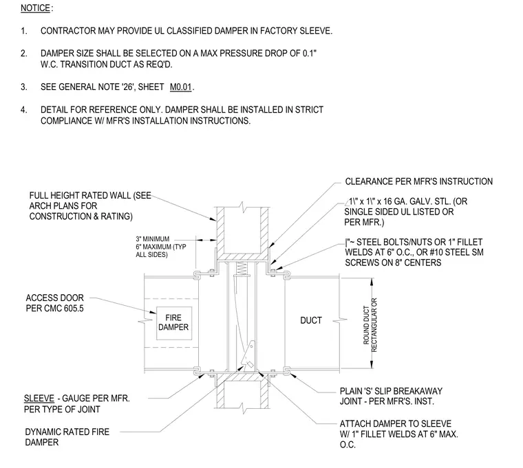
A dynamic rated fire damper is mounted within a sleeve installed in a full-height rated wall, maintaining a three to six inch clearance on all sides per manufacturer instructions. The damper connects to the sleeve using one-inch fillet welds at six inches maximum on center. A one-inch by one-inch by sixteen gauge galvanized steel angle or single-sided UL-listed angle secures the assembly to the wall opening. Ductwork attaches to the sleeve with a plain 'S' slip breakaway joint or alternative approved fasteners. An access door is provided per CMC section 605.5.
3" MINIMUM 6" MAXIMUM (TYP ALL SIDES) ROUND DUCT RECTANGULAR OR FIRE DAMPER DYNAMIC RATED FIRE DAMPER DUCT CLEARANCE PER MFR'S INSTRUCTION |"~ STEEL BOLTS/NUTS OR 1" FILLET WELDS AT 6" O.C., OR #10 STEEL SM SCREWS ON 8" CENTERS NOTICE: 1. CONTRACTOR MAY PROVIDE UL CLASSIFIED DAMPER IN FACTORY SLEEVE. 2. DAMPER SIZE SHALL BE SELECTED ON A MAX PRESSURE DROP OF 0.1" W.C. TRANSITION DUCT AS REQ'D. 3. SEE GENERAL NOTE '26', SHEET M0.01. 4. DETAIL FOR REFERENCE ONLY. DAMPER SHALL BE INSTALLED IN STRICT COMPLIANCE W/ MFR'S INSTALLATION INSTRUCTIONS. 1\" x 1\" x 16 GA. GALV. STL. (OR SINGLE SIDED UL LISTED OR PER MFR.) FULL HEIGHT RATED WALL (SEE ARCH PLANS FOR CONSTRUCTION & RATING) ACCESS DOOR PER CMC 605.5 SLEEVE - GAUGE PER MFR. PER TYPE OF JOINT PLAIN 'S' SLIP BREAKAWAY JOINT - PER MFR'S. INST. ATTACH DAMPER TO SLEEVE W/ 1" FILLET WELDS AT 6" MAX. O.C.
Members view this detail in full resolution, download the CAD files (SVG, PDF), and can adapt it in the built-in CAD editor — export DXF, DWG, or PDF.
Start membership