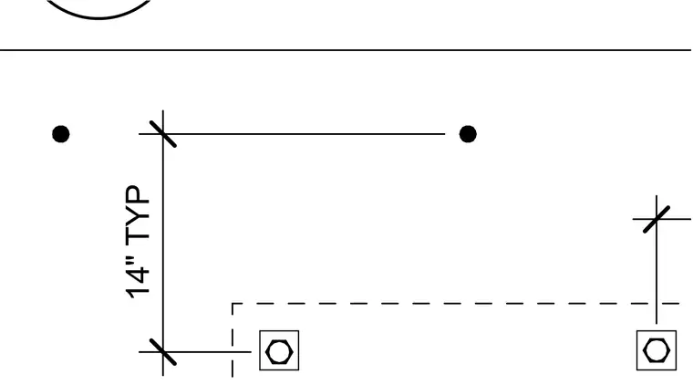
This drawing indicates a mechanical support detail with a typical fourteen-inch dimension spacing. Hex nuts and dashed hidden lines represent concealed anchoring or framing components. A solid horizontal line bounds the top of the detail.
Members view this detail in full resolution, download the CAD files (SVG, PDF), and open any detail in the built-in CAD editor to edit and export DXF or DWG.
Sign in to subscribe