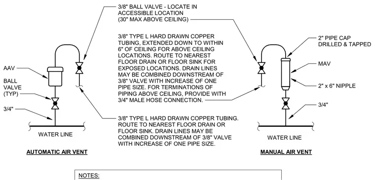
An automatic air vent or a manual air vent connects to a main water line via a three-quarter-inch pipe fitted with a typical ball valve. The manual vent utilizes a two-inch by six-inch nipple capped with a drilled and tapped two-inch pipe cap. Both configurations route discharge through three-eighths-inch Type L hard-drawn copper tubing extending down to within six inches of the ceiling for above-ceiling locations or directly to the nearest floor drain or sink for exposed locations. Drain lines combine downstream of the three-eighths-inch valve with an increase of one pipe size, and piping terminating above the ceiling includes a three-quarter-inch male hose connection. An accessible three-eighths-inch ball valve is positioned a maximum of thirty inches above the ceiling.
AUTOMATIC AIR VENT MANUAL AIR VENT 2" PIPE CAP DRILLED & TAPPED 2" x 6" NIPPLE 3/8" TYPE L HARD DRAWN COPPER TUBING. ROUTE TO NEAREST FLOOR DRAIN OR FLOOR SINK. DRAIN LINES MAY BE COMBINED DOWNSTREAM OF 3/8" VALVE WITH INCREASE OF ONE PIPE SIZE. 3/8" TYPE L HARD DRAWN COPPER TUBING, EXTENDED DOWN TO WITHIN 6" OF CEILING FOR ABOVE CEILING LOCATIONS. ROUTE TO NEAREST FLOOR DRAIN OR FLOOR SINK FOR EXPOSED LOCATIONS. DRAIN LINES MAY BE COMBINED DOWNSTREAM OF 3/8" VALVE WITH INCREASE OF ONE PIPE SIZE. FOR TERMINATIONS OF PIPING ABOVE CEILING, PROVIDE WITH 3/4" MALE HOSE CONNECTION. AAV WATER LINE WATER LINE MAV NOTES: 3/8" BALL VALVE - LOCATE IN ACCESSIBLE LOCATION (30" MAX ABOVE CEILING) BALL VALVE (TYP) 3/4" 3/4"
Members view this detail in full resolution, download the CAD files (SVG, PDF), and can adapt it in the built-in CAD editor — export DXF, DWG, or PDF.
Start membership