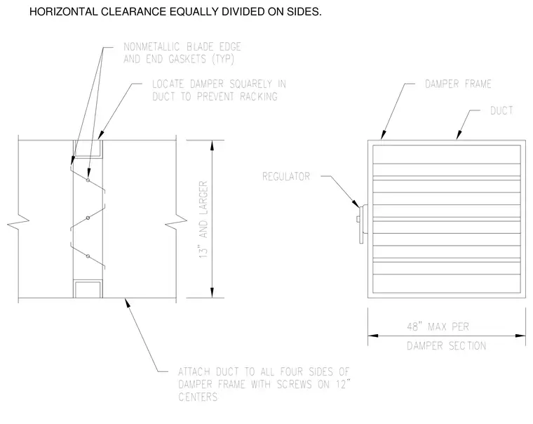
The damper frame is mounted squarely inside the duct with equal horizontal clearance on both sides to prevent racking. Nonmetallic blade edge and end gaskets are provided on dampers thirteen inches and larger. The duct is attached to all four sides of the damper frame using screws spaced at twelve inches on centers. A regulator operates the opposed blade damper section, which spans a maximum of forty-eight inches.
HORIZONTAL CLEARANCE EQUALLY DIVIDED ON SIDES. DAMPER SECTION 48" MAX PER 13" AND LARGER NONMETALLIC BLADE EDGE AND END GASKETS (TYP) LOCATE DAMPER SQUARELY IN DUCT TO PREVENT RACKING DAMPER FRAME DUCT REGULATOR ATTACH DUCT TO ALL FOUR SIDES OF DAMPER FRAME WITH SCREWS ON 12" CENTERS
Members view this detail in full resolution, download the CAD files (SVG, PDF), and can adapt it in the built-in CAD editor — export DXF, DWG, or PDF.
Start membership