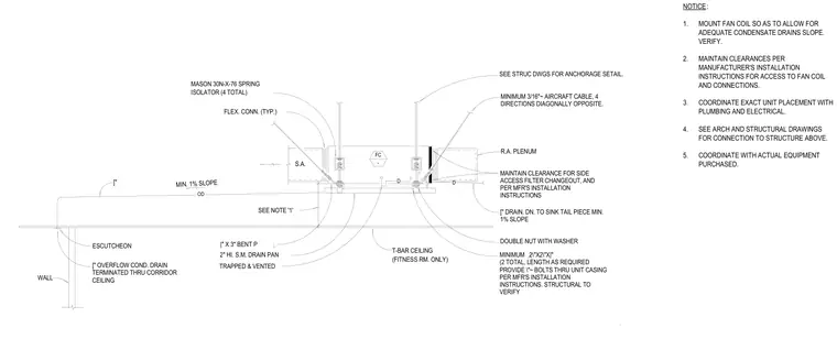
Suspended fan coil unit installation above a T-bar ceiling. The unit is supported by four total Mason spring isolators connected via bent plates, with double nuts and washers. Four minimum three-sixteenth-inch aircraft cables provide diagonal seismic bracing in four directions. A minimum two-inch-high sheet metal drain pan is located beneath the unit, connected to a trapped and vented drain line with a minimum one percent slope down to a sink tailpiece. An overflow condensate drain line terminates through the corridor ceiling with an escutcheon. Flexible connections tie into the supply air and return air plenums, maintaining clearances for side access and filter changout.
FLEX. CONN. (TYP.) [" MIN. 1% SLOPE DOUBLE NUT WITH WASHER SEE NOTE '1' MAINTAIN CLEARANCE FOR SIDE ACCESS FILTER CHANGEOUT, AND PER MFR'S INSTALLATION INSTRUCTIONS |" X 3" BENT P S.A. SEE STRUC DWGS FOR ANCHORAGE SETAIL. R.A. PLENUM ISOLATOR (4 TOTAL) MASON 30N-X-76 SPRING OD D WALL [" OVERFLOW COND. DRAIN TERMINATED THRU CORRIDOR CEILING ESCUTCHEON D 2" HI. S.M. DRAIN PAN [" DRAIN. DN. TO SINK TAIL PIECE MIN. 1% SLOPE TRAPPED & VENTED T-BAR CEILING (FITNESS RM. ONLY) NOTICE: 1. MOUNT FAN COIL SO AS TO ALLOW FOR ADEQUATE CONDENSATE DRAINS SLOPE. VERIFY. 2. MAINTAIN CLEARANCES PER MANUFACTURER'S INSTALLATION INSTRUCTIONS FOR ACCESS TO FAN COIL AND CONNECTIONS. 3. COORDINATE EXACT UNIT PLACEMENT WITH PLUMBING AND ELECTRICAL. 4. SEE ARCH AND STRUCTURAL DRAWINGS FOR CONNECTION TO STRUCTURE ABOVE. 5. COORDINATE WITH ACTUAL EQUIPMENT PURCHASED. MINIMUM 3/16"~ AIRCRAFT CABLE, 4 DIRECTIONS DIAGONALLY OPPOSITE. MINIMUM 2\"X2\"X|" (2 TOTAL, LENGTH AS REQUIRED PROVIDE \"~ BOLTS THRU UNIT CASING PER MFR'S INSTALLATION INSTRUCTIONS. STRUCTURAL TO VERIFY FC -
Members view this detail in full resolution, download the CAD files (SVG, PDF), and can adapt it in the built-in CAD editor — export DXF, DWG, or PDF.
Start membership