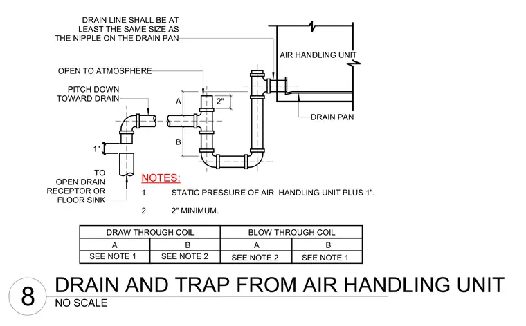
The condensate drain line connects to the drain pan nipple of the air handling unit, matching or exceeding the nipple size. Piping drops down to a P-trap configured with specific dimensions A and B determined by whether the unit is draw-through or blow-through. A two-inch minimum height and atmospheric vent are maintained. The horizontal run pitches downward toward the drain, terminating with a one-inch air gap above an open drain receptor or floor sink.
DRAW THROUGH COIL BLOW THROUGH COIL A B SEE NOTE 1 SEE NOTE 2 SEE NOTE 1 SEE NOTE 2 A B DRAIN LINE SHALL BE AT LEAST THE SAME SIZE AS THE NIPPLE ON THE DRAIN PAN PITCH DOWN TOWARD DRAIN AIR HANDLING UNIT DRAIN PAN NOTES: 1. STATIC PRESSURE OF AIR HANDLING UNIT PLUS 1". 2. 2" MINIMUM. 1" B A 2" TO OPEN DRAIN RECEPTOR OR FLOOR SINK OPEN TO ATMOSPHERE NO SCALE 8 DRAIN AND TRAP FROM AIR HANDLING UNIT
Members view this detail in full resolution, download the CAD files (SVG, PDF), and can adapt it in the built-in CAD editor — export DXF, DWG, or PDF.
Start membership