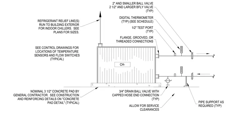
Chillers connect to piping systems utilizing flanged, grooved, or threaded connections with ball valves or butterfly valves depending on pipe size. Digital thermometers and test ports are integrated into the piping runs typical of mechanical equipment installations. A three-quarter-inch drain ball valve with a capped hose end connection provides drainage capabilities. The chiller unit rests upon a nominal three-and-a-half-inch concrete pad provided by the general contractor, with pipe supports installed as required to maintain service clearances.
2" AND SMALLER BALL VALVE 2 1/2" AND LARGER BFLY VALVE (TYP) DIGITAL THERMOMETER (TYP) (SEE SCHEDULE) 1/2" TEST PORT (TYP) FLANGE, GROOVED, OR THREADED CONNECTIONS 3/4" DRAIN BALL VALVE WITH CAPPED HOSE END CONNECTION (TYP) ALLOW FOR SERVICE CLEARANCES PIPE SUPPORT AS REQUIRED (TYP) NOMINAL 3 1/2" CONCRETE PAD BY GENERAL CONTRACTOR. SEE CONSTRUCTION AND REINFORCING DETAILS ON "CONCRETE PAD DETAIL" (TYPICAL) REFRIGERANT RELIEF LINE(S) RUN TO BUILDING EXTERIOR FOR INDOOR CHILLERS. SEE PLANS FOR SIZES. CH- SEE CONTROL DRAWINGS FOR LOCATIONS OF TEMPERATURE SENSORS AND FLOW SWITCHES (TYPICAL)
Members view this detail in full resolution, download the CAD files (SVG, PDF), and can adapt it in the built-in CAD editor — export DXF, DWG, or PDF.
Start membership