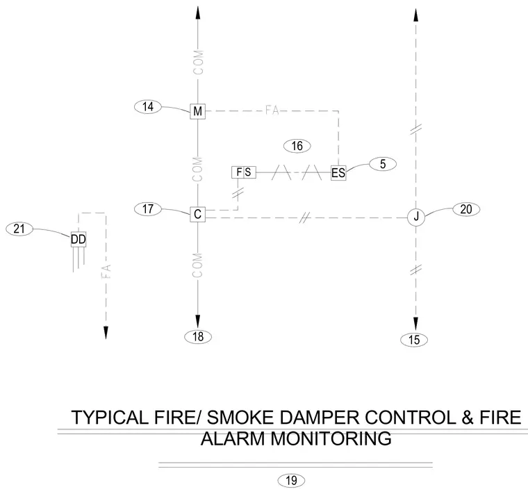
This diagram details the control wiring and fire alarm monitoring interconnections for a typical fire and smoke damper system. It maps out the communication lines and fire alarm interfaces linked to the damper actuator and control sensors. Numbered reference bubbles and dashed lines indicate signal routing and terminal connections.
F S ES M C DD 20 15 J 16 FA 18 COM COM 17 14 19 FA 21 COM 5 TYPICAL FIRE/ SMOKE DAMPER CONTROL & FIRE ALARM MONITORING
Members view this detail in full resolution, download the CAD files (SVG, PDF), and can adapt it in the built-in CAD editor — export DXF, DWG, or PDF.
Start membership