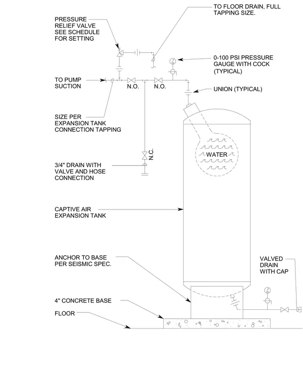
A captive air expansion tank rests on a four-inch concrete base anchored to the floor per seismic specifications. The top piping connection features a pressure relief valve set per schedule, a zero-to-one-hundred PSI pressure gauge with a cock, and unions typically installed adjacent to the tank. Piping routes to the pump suction with sizing matching the expansion tank connection tapping. A three-quarter-inch drain includes a valve and hose connection, alongside normally closed and normally open valves and a valved drain with a cap. Full tapping size lines lead to the floor drain.
N.C. GAUGE WITH COCK 0-100 PSI PRESSURE TO FLOOR DRAIN, FULL SEE SCHEDULE RELIEF VALVE TO PUMP CONNECTION TAPPING EXPANSION TANK VALVE AND HOSE 3/4" DRAIN WITH 4" CONCRETE BASE FLOOR PER SEISMIC SPEC. ANCHOR TO BASE DRAIN EXPANSION TANK CAPTIVE AIR WATER N.O. SUCTION SIZE PER CONNECTION N.O. PRESSURE FOR SETTING WITH CAP VALVED (TYPICAL) TAPPING SIZE. UNION (TYPICAL) P P
Members view this detail in full resolution, download the CAD files (SVG, PDF), and can adapt it in the built-in CAD editor — export DXF, DWG, or PDF.
Start membership