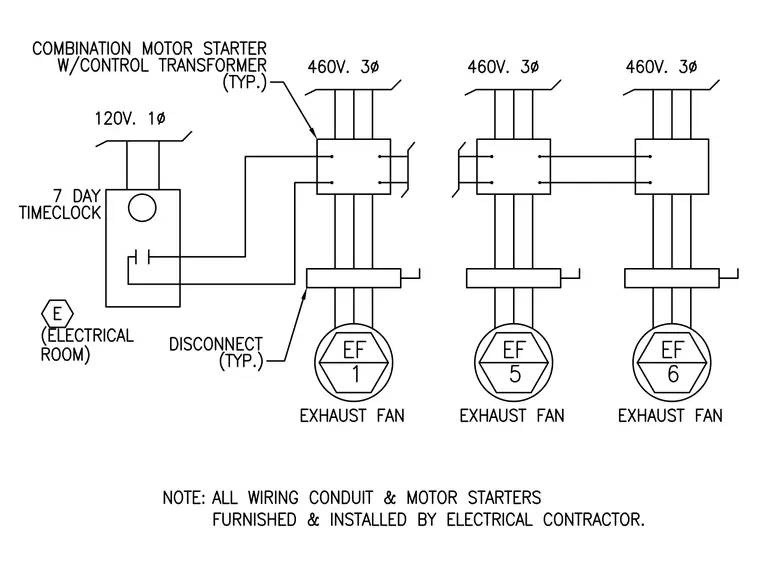
An electrical wiring schematic shows three 460-volt three-phase exhaust fans controlled by individual combination motor starters with control transformers. A seven-day timeclock operating at 120-volt single-phase interfaces with the motor starter for exhaust fan one located in the electrical room. Disconnect switches are provided for each exhaust fan circuit. All wiring, conduit, and motor starters are furnished and installed by the electrical contractor.
Members view this detail in full resolution, download the CAD files (SVG, PDF), and can adapt it in the built-in CAD editor — export DXF, DWG, or PDF.
Start membership