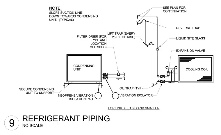
This diagram details the refrigerant piping schematic for HVAC systems with units five tons and smaller, connecting a condensing unit to a cooling coil. The condensing unit is secured to its support using neoprene vibration isolation pads and vibration isolators. The suction line is sloped downward toward the condensing unit typically, with lift traps installed every twenty-five feet of rise and a reverse trap at high points. Additional system components include a filter-drier, a liquid sight glass, and an expansion valve near the cooling coil.
FOR UNITS 5 TONS AND SMALLER NEOPRENE VIBRATION ISOLATION PAD OIL TRAP (TYP) FILTER-DRIER (FOR TYPE AND LOCATION SEE SPEC) VIBRATION ISOLATOR SECURE CONDENSING UNIT TO SUPPORT EXPANSION VALVE COOLING COIL CONDENSING UNIT LIFT TRAP (EVERY 25 FT. OF RISE) LIQUID SITE GLASS REVERSE TRAP SEE PLAN FOR CONTINUATION SLOPE SUCTION LINE DOWN TOWARDS CONDENSING UNIT. (TYPICAL) NOTE: NO SCALE 9 REFRIGERANT PIPING
Members view this detail in full resolution, download the CAD files (SVG, PDF), and can adapt it in the built-in CAD editor — export DXF, DWG, or PDF.
Start membership