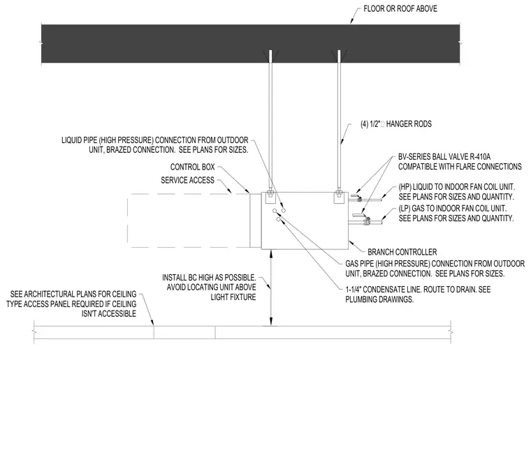
The branch controller unit is suspended from the floor or roof structure above using four one-half-inch diameter threaded hanger rods. High-pressure liquid and gas refrigerant lines connect from the outdoor unit via brazed connections, while R-410A compatible ball valves manage the liquid and gas lines running to the indoor fan coil unit. A one-and-one-quarter-inch condensate line routes from the unit to a building drain per plumbing drawings. The unit requires service access to the control box and must be installed as high as possible while avoiding locations directly above light fixtures. An architectural ceiling type access panel is required if the surrounding ceiling is inaccessible.
BRANCH CONTROLLER (4) 1/2"∅ HANGER RODS FLOOR OR ROOF ABOVE (HP) LIQUID TO INDOOR FAN COIL UNIT. SEE PLANS FOR SIZES AND QUANTITY. (LP) GAS TO INDOOR FAN COIL UNIT. SEE PLANS FOR SIZES AND QUANTITY. BV-SERIES BALL VALVE R-410A COMPATIBLE WITH FLARE CONNECTIONS GAS PIPE (HIGH PRESSURE) CONNECTION FROM OUTDOOR UNIT, BRAZED CONNECTION. SEE PLANS FOR SIZES. 1-1/4" CONDENSATE LINE. ROUTE TO DRAIN. SEE PLUMBING DRAWINGS. SERVICE ACCESS CONTROL BOX LIQUID PIPE (HIGH PRESSURE) CONNECTION FROM OUTDOOR UNIT, BRAZED CONNECTION. SEE PLANS FOR SIZES. SEE ARCHITECTURAL PLANS FOR CEILING TYPE ACCESS PANEL REQUIRED IF CEILING ISN'T ACCESSIBLE INSTALL BC HIGH AS POSSIBLE. AVOID LOCATING UNIT ABOVE LIGHT FIXTURE
Members view this detail in full resolution, download the CAD files (SVG, PDF), and can adapt it in the built-in CAD editor — export DXF, DWG, or PDF.
Start membership