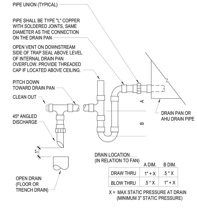
The condensate drain piping consists of Type L copper pipe with soldered joints matching the diameter of the drain pan connection. A pipe union is installed near the air handling unit drain pan for maintenance access. The trap configuration requires specific A and B dimensions determined by whether the drain location is draw-thru or blow-thru relative to the fan, where X represents the maximum static pressure with a minimum three-inch static pressure. An open vent is positioned on the downstream side of the trap seal above the level of the internal drain pan overflow, with a threaded cap provided if located above a ceiling. The horizontal run pitches down toward the drain pan. A cleanout with a forty-five degree angled discharge terminates one inch above an open floor or trench drain.
DRAIN LOCATION (IN RELATION TO FAN) A DIM. B DIM. DRAW THRU BLOW THRU 1" + X 1" + X .5 * X .5 * X X = MAX STATIC PRESSURE AT DRAIN (MINIMUM 3" STATIC PRESSURE) OPEN DRAIN (FLOOR OR TRENCH DRAIN) 0'-3 23/32" 1" 45º ANGLED DISCHARGE CLEAN OUT PITCH DOWN TOWARD DRAIN PAN OPEN VENT ON DOWNSTREAM SIDE OF TRAP SEAL ABOVE LEVEL OF INTERNAL DRAIN PAN OVERFLOW. PROVIDE THREADED CAP IF LOCATED ABOVE CEILING. PIPE SHALL BE TYPE "L" COPPER WITH SOLDERED JOINTS, SAME DIAMETER AS THE CONNECTION ON THE DRAIN PAN PIPE UNION (TYPICAL) DRAIN PAN OR AHU DRAIN PIPE A B
Members view this detail in full resolution, download the CAD files (SVG, PDF), and can adapt it in the built-in CAD editor — export DXF, DWG, or PDF.
Start membership