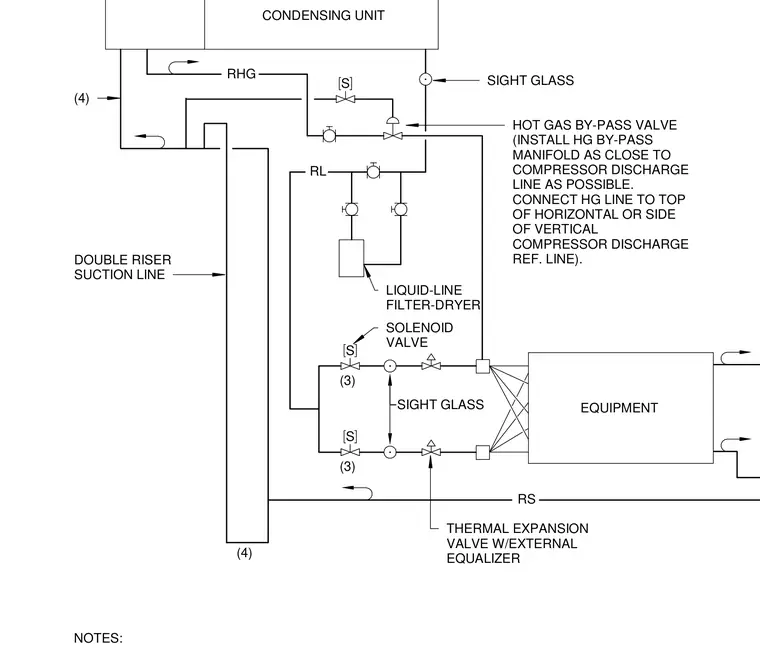
The refrigerant flow diagram details the piping layout and equipment connections for a condensing unit and connected mechanical equipment. A double riser suction line connects to the circuit with a hot gas bypass valve installed close to the compressor discharge line. Liquid line filter-dryers, solenoid valves, sight glasses, and thermal expansion valves with external equalizers are incorporated along the refrigerant lines.
S S S NOTES: (4) (4) SIGHT GLASS (3) RL RHG CONDENSING UNIT EQUIPMENT RS SIGHT GLASS (3) THERMAL EXPANSION VALVE W/EXTERNAL EQUALIZER DOUBLE RISER SUCTION LINE HOT GAS BY-PASS VALVE (INSTALL HG BY-PASS MANIFOLD AS CLOSE TO COMPRESSOR DISCHARGE LINE AS POSSIBLE. CONNECT HG LINE TO TOP OF HORIZONTAL OR SIDE OF VERTICAL COMPRESSOR DISCHARGE REF. LINE). LIQUID-LINE FILTER-DRYER SOLENOID VALVE
Members view this detail in full resolution, download the CAD files (SVG, PDF), and can adapt it in the built-in CAD editor — export DXF, DWG, or PDF.
Start membership