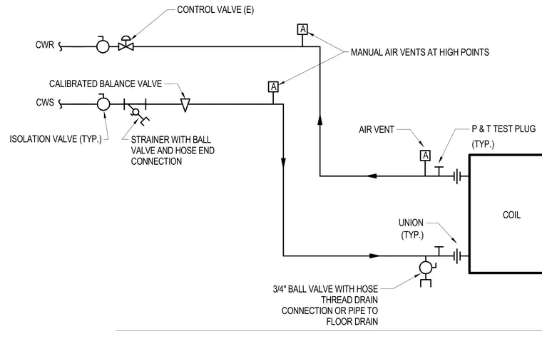
This diagram details the chilled water coil piping arrangement featuring a control valve on the chilled water return line and a calibrated balance valve, strainer with ball valve and hose end connection, and isolation valves on the chilled water supply. Pressure and temperature test plugs and unions are installed at the coil connections. Manual air vents are positioned at high points, and a three-quarter-inch ball valve with a hose thread drain connection routes to a floor drain.
A A A (TYP.) (TYP.) UNION CONTROL VALVE (E) AIR VENT P & T TEST PLUG CWR CWS ISOLATION VALVE (TYP.) COIL STRAINER WITH BALL VALVE AND HOSE END CONNECTION 3/4" BALL VALVE WITH HOSE THREAD DRAIN CONNECTION OR PIPE TO FLOOR DRAIN MANUAL AIR VENTS AT HIGH POINTS CALIBRATED BALANCE VALVE
Members view this detail in full resolution, download the CAD files (SVG, PDF), and can adapt it in the built-in CAD editor — export DXF, DWG, or PDF.
Start membership