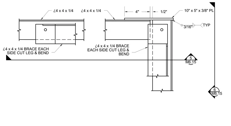
A mechanical hood mounting assembly in plan view incorporates four-by-four by one-quarter-inch structural steel angles used as bracing on each side with cut and bent legs. A ten-by-five by three-eighths-inch steel plate ties the assembly together with three-sixteenth-inch typical fillet welds. Spacings of four inches and one-half inch define the plate positioning.
∠ 4 x 4 x 1/4 ∠ 4 x 4 x 1/4 4" 1/2" 10" x 5" x 3/8" PL 3/16" TYP ∠ 4 x 4 x 1/4 BRACE EACH SIDE CUT LEG & BEND ∠ 4 x 4 x 1/4 BRACE EACH SIDE CUT LEG & BEND 5 M6.15 6 M6.15
Members view this detail in full resolution, download the CAD files (SVG, PDF), and can adapt it in the built-in CAD editor — export DXF, DWG, or PDF.
Start membership