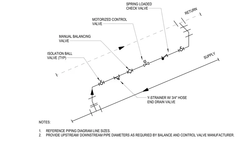
This piping arrangement connects the supply and return mains using a bypass line equipped with an isolation ball valve typically, a Y-strainer with a three-quarter-inch hose end drain valve, a manual balancing valve, a motorized control valve, and a spring-loaded check valve. Piping line sizes reference the main diagrams, and upstream and downstream pipe diameters are provided as required by the balance and control valve manufacturer.
S M RETURN SUPPLY SPRING LOADED CHECK VALVE MOTORIZED CONTROL VALVE MANUAL BALANCING VALVE ISOLATION BALL VALVE (TYP) Y-STRAINER W/ 3/4" HOSE END DRAIN VALVE NOTES: 1. REFERENCE PIPING DIAGRAM LINE SIZES. 2. PROVIDE UPSTREAM/ DOWNSTREAM PIPE DIAMETERS AS REQURIED BY BALANCE AND CONTROL VALVE MANUFACTURER.
Members view this detail in full resolution, download the CAD files (SVG, PDF), and can adapt it in the built-in CAD editor — export DXF, DWG, or PDF.
Start membership