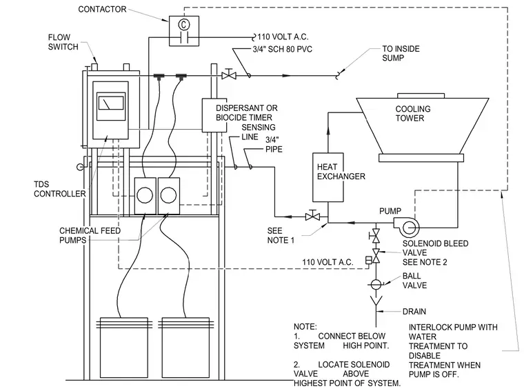
The cooling tower water treatment system integrates a total dissolved solids controller connected via a contactor to a 110-volt alternating current supply and interlocked with the water treatment pump to disable treatment when the pump is off. Chemical feed pumps deliver dispersants or biocides through three-quarter-inch schedule 80 PVC sensing and feed lines connected below the system high point. The layout includes a heat exchanger, a flow switch, solenoid bleed and ball valves with the solenoid valve located above the highest point of the system, and a drain discharging to the inside sump.
TO INSIDE SUMP 110 VOLT A.C. C INTERLOCK PUMP WITH WATER TREATMENT TO DISABLE TREATMENT WHEN PUMP IS OFF. NOTE: 1. CONNECT BELOW SYSTEM HIGH POINT. 2. LOCATE SOLENOID VALVE ABOVE HIGHEST POINT OF SYSTEM. SEE NOTE 1 SENSING LINE DISPERSANT OR BIOCIDE TIMER DRAIN BALL VALVE SOLENOID BLEED VALVE SEE NOTE 2 PUMP COOLING TOWER 110 VOLT A.C. CHEMICAL FEED PUMPS TDS CONTROLLER 3/4" PIPE HEAT EXCHANGER 3/4" SCH 80 PVC FLOW SWITCH CONTACTOR
Members view this detail in full resolution, download the CAD files (SVG, PDF), and can adapt it in the built-in CAD editor — export DXF, DWG, or PDF.
Start membership