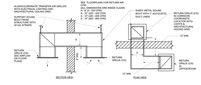
Section and plan views of a transfer air system incorporate a sheet metal sound boot lined with one-inch acoustic duct liner. The sound boot is suspended from the overhead structure using twenty gauge straps with a twelve inch minimum clearance. Return grilles are coordinated with the architectural ceiling grid and electrical lighting, maintaining a six inch minimum clearance above the finished ceiling. Sizing dimensions for dimension A range from eight inches for zero to two hundred CFM up to fourteen inches for six hundred to eight hundred CFM.
SECTION VIEW PLAN VIEW SHEET METAL SOUND BOOT WITH 1" ACCOUSTIC DUCT LINER SUPPORT SOUND BOOT FROM STRUCTURE WITH 20 GA. STRAPS 12" MIN. 12" MIN. 6" MIN. ALIGN/COORDINATE TRANSFER AIR GRILLES WITH ELECTRICAL LIGHTING AND ARCHITECTURAL CEILING GRID. RETURN GRILLE (CG) SEE AIRFLOW ON FLOOR PLANS RETURN GRILLE (CG) IN OFFICE/ROOM RETURN GRILLE (CG) RETURN GRILLE (CG) IN CORRIDOR. COORDINATE LOCATION WITH LIGHTS & ARCHITECTURAL CEILING GRID. SEE FLOORPLANS FOR RETURN AIR CFM: (ALL DIMENSIONS ARE INSIDE CLEAR) A - 8" (0 - 200 CFM) A - 10" (200 - 400 CFM) A - 12" (400 - 600 CFM) A - 14" (600 - 800 CFM) A A
Members view this detail in full resolution, download the CAD files (SVG, PDF), and can adapt it in the built-in CAD editor — export DXF, DWG, or PDF.
Start membership