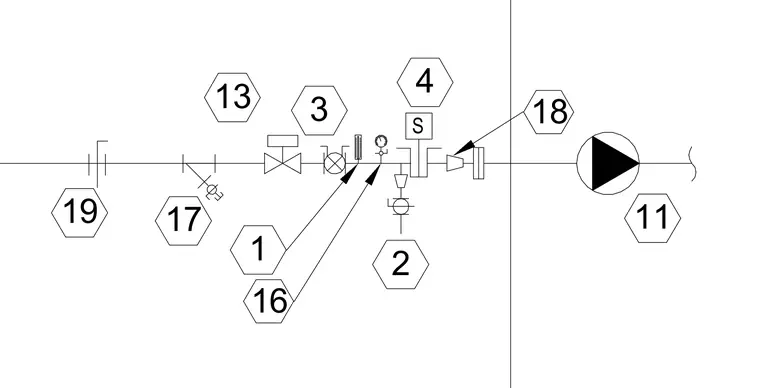
Mechanical piping schematic showing a fluid line routed from a pump through various inline control components, valves, and measurement devices. The run includes a pump, strainer, flow meter, pressure gauge, and isolation valves identified by numbered hexagon tags.
Members view this detail in full resolution, download the CAD files (SVG, PDF), and can adapt it in the built-in CAD editor — export DXF, DWG, or PDF.
Start membership