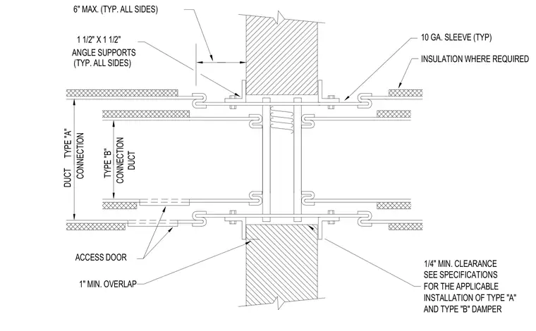
A fire damper is installed within a wall penetration using a ten-gauge steel sleeve with a one-fourth-inch minimum clearance. One-and-a-half-inch by one-and-a-half-inch angle supports are secured to all sides of the sleeve with a maximum six-inch offset from the wall face. Ductwork connects to the sleeve using Type A and Type B connections with an access door providing a one-inch minimum overlap. Insulation is applied to the ductwork where required per specifications.
ACCESS DOOR 1" MIN. OVERLAP CONNECTION DUCT TYPE "A" CONNECTION TYPE "B" DUCT 6" MAX. (TYP. ALL SIDES) ANGLE SUPPORTS (TYP. ALL SIDES) 1 1/2" X 1 1/2" INSTALLATION OF TYPE "A" FOR THE APPLICABLE SEE SPECIFICATIONS AND TYPE "B" DAMPER 1/4" MIN. CLEARANCE INSULATION WHERE REQUIRED 10 GA. SLEEVE (TYP)
Members view this detail in full resolution, download the CAD files (SVG, PDF), and can adapt it in the built-in CAD editor — export DXF, DWG, or PDF.
Start membership