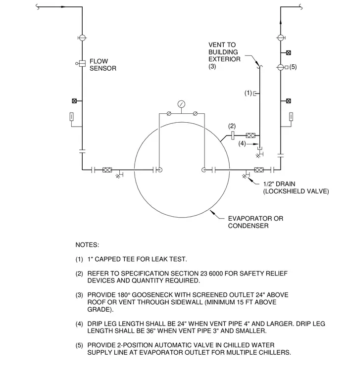
Piping connections for a chiller evaporator or condenser, including a flow sensor and a vent line extending to the building exterior with a one-inch capped tee for leak testing. A safety relief device is connected with specific requirements detailed in specification section 23 6000. Vent pipes terminate with a one hundred eighty degree gooseneck and screened outlet twenty-four inches above the roof or through a sidewall at least fifteen feet above grade. Drip leg length is specified as twenty-four inches for vent pipes four inches and larger, and thirty-six inches for pipes three inches and smaller. A two-position automatic valve is installed in the chilled water supply line at the evaporator outlet for multiple chillers, alongside a half-inch drain with a lockshield valve.
(2) (1) NOTES: (1) 1" CAPPED TEE FOR LEAK TEST. (2) REFER TO SPECIFICATION SECTION 23 6000 FOR SAFETY RELIEF DEVICES AND QUANTITY REQUIRED. (3) PROVIDE 180° GOOSENECK WITH SCREENED OUTLET 24" ABOVE ROOF OR VENT THROUGH SIDEWALL (MINIMUM 15 FT ABOVE GRADE). (4) DRIP LEG LENGTH SHALL BE 24" WHEN VENT PIPE 4" AND LARGER. DRIP LEG LENGTH SHALL BE 36" WHEN VENT PIPE 3" AND SMALLER. (5) PROVIDE 2-POSITION AUTOMATIC VALVE IN CHILLED WATER SUPPLY LINE AT EVAPORATOR OUTLET FOR MULTIPLE CHILLERS. 1/2" DRAIN (LOCKSHIELD VALVE) (4) (5) EVAPORATOR OR CONDENSER FLOW SENSOR VENT TO BUILDING EXTERIOR (3)
Members view this detail in full resolution, download the CAD files (SVG, PDF), and can adapt it in the built-in CAD editor — export DXF, DWG, or PDF.
Start membership