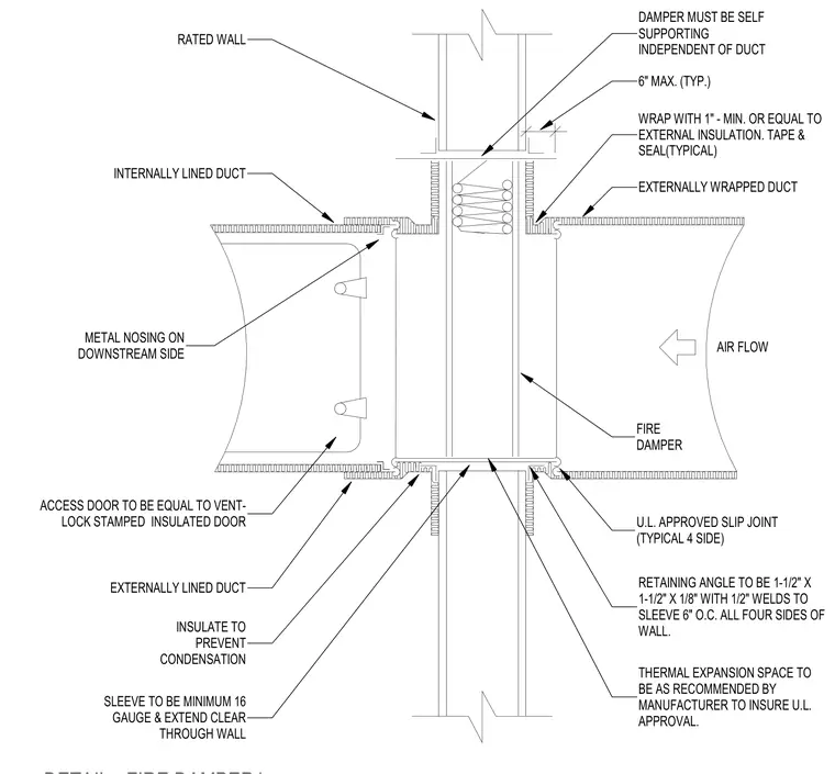
A fire damper is installed inside a minimum sixteen-gauge steel sleeve that extends clear through the rated wall penetration. The damper must remain self-supporting and independent of the connecting ductwork. Retaining angles measuring one-and-a-half by one-and-a-half by one-eighth inches attach to the sleeve with half-inch welds spaced six inches on center on all four sides of the wall. Underwriters Laboratories approved slip joints connect the assembly on all four sides, maintaining a thermal expansion space per manufacturer recommendations. An externally lined duct includes an access door equal to a Ventlock stamped insulated door, with a metal nosing on the downstream side and external insulation wrapped, taped, and sealed.
SLEEVE TO BE MINIMUM 16 GAUGE & EXTEND CLEAR THROUGH WALL EXTERNALLY LINED DUCT ACCESS DOOR TO BE EQUAL TO VENT- LOCK STAMPED INSULATED DOOR INSULATE TO PREVENT CONDENSATION INTERNALLY LINED DUCT METAL NOSING ON DOWNSTREAM SIDE THERMAL EXPANSION SPACE TO BE AS RECOMMENDED BY MANUFACTURER TO INSURE U.L. APPROVAL. RETAINING ANGLE TO BE 1-1/2" X 1-1/2" X 1/8" WITH 1/2" WELDS TO SLEEVE 6" O.C. ALL FOUR SIDES OF WALL. WRAP WITH 1" - MIN. OR EQUAL TO EXTERNAL INSULATION. TAPE & SEAL(TYPICAL) U.L. APPROVED SLIP JOINT (TYPICAL 4 SIDE) FIRE DAMPER AIR FLOW 6" MAX. (TYP.) EXTERNALLY WRAPPED DUCT DAMPER MUST BE SELF SUPPORTING INDEPENDENT OF DUCT RATED WALL
Members view this detail in full resolution, download the CAD files (SVG, PDF), and can adapt it in the built-in CAD editor — export DXF, DWG, or PDF.
Start membership