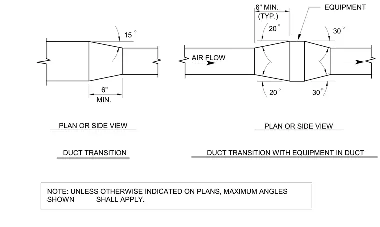
These duct transition diagrams establish maximum taper angles and minimum length requirements for HVAC sheet metal work. The standard transition specifies a maximum fifteen-degree transition angle over a minimum six-inch length. The equipment transition details inline equipment with a twenty-degree approach angle and a thirty-degree discharge angle, maintaining a minimum six-inch typical clearance. Unless otherwise indicated on plans, the maximum angles shown shall apply to all duct transitions.
DUCT TRANSITION PLAN OR SIDE VIEW PLAN OR SIDE VIEW NOTE: UNLESS OTHERWISE INDICATED ON PLANS, MAXIMUM ANGLES SHOWN SHALL APPLY. EQUIPMENT AIR FLOW 20 30 30 15 20 DUCT TRANSITION WITH EQUIPMENT IN DUCT 6" MIN. 6" MIN. (TYP.)
Members view this detail in full resolution, download the CAD files (SVG, PDF), and can adapt it in the built-in CAD editor — export DXF, DWG, or PDF.
Start membership