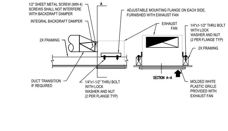
An exhaust fan unit is secured to 2x wood framing using adjustable mounting flanges on each side fastened with 1/4" by 1-1/2" through bolts, lock washers, and nuts, using two bolts per flange typical. A molded white plastic grille is provided with the exhaust fan at the ceiling finish line. An integral backdraft damper connects to a duct transition via at least four 1/2" sheet metal screws positioned to avoid interfering with the damper operation.
DUCT TRANSITION IF REQUIRED INTEGRAL BACKDRAFT DAMPER 2X FRAMING 1/2" SHEET METAL SCREW (MIN 4) SCREWS SHALL NOT INTERFERE WITH BACKDRAFT DAMPER EXHAUST FAN ADJUSTABLE MOUNTING FLANGE ON EACH SIDE, FURNISHED WITH EXHAUST FAN 1/4"x1-1/2" THRU BOLT WITH LOCK WASHER AND NUT (2 PER FLANGE TYP) 1/4"x1-1/2" THRU BOLT WITH LOCK WASHER AND NUT (2 PER FLANGE TYP) 2X FRAMING MOLDED WHITE PLASTIC GRILLE PROVIDED WITH EXHAUST FAN
Members view this detail in full resolution, download the CAD files (SVG, PDF), and can adapt it in the built-in CAD editor — export DXF, DWG, or PDF.
Start membership