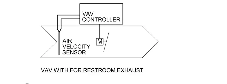
This control diagram outlines the configuration for a variable air volume terminal unit equipped with a VAV controller, an air velocity sensor, and a motorized damper for restroom exhaust. The VAV controller interfaces with the air velocity sensor positioned within the ductwork to monitor airflow. An integrated actuator modulates the damper to maintain specified airflow rates for exhaust requirements.
Members view this detail in full resolution, download the CAD files (SVG, PDF), and can adapt it in the built-in CAD editor — export DXF, DWG, or PDF.
Start membership