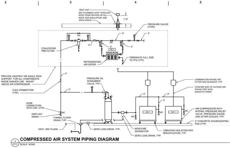
Compressed air system piping diagram illustrating air compressors mounted on a four inch concrete housekeeping pad with vibration isolation and internal pressure relief valves. The piping layout incorporates combination intake air filters and silencers, moisture separators, a coalescing pre-filter, and a refrigerated air dryer with associated pressure gauges and normally closed valves. A receiver tank connects to the main three inch distribution line, which includes flexible connections, drip leg drains, and hose connections with caps terminating at funnel floor drains. The system vents through the roof via a vent cap utilizing a plumbing vent through roof penetration detail.
Members view this detail in full resolution, download the CAD files (SVG, PDF), and can adapt it in the built-in CAD editor — export DXF, DWG, or PDF.
Start membership