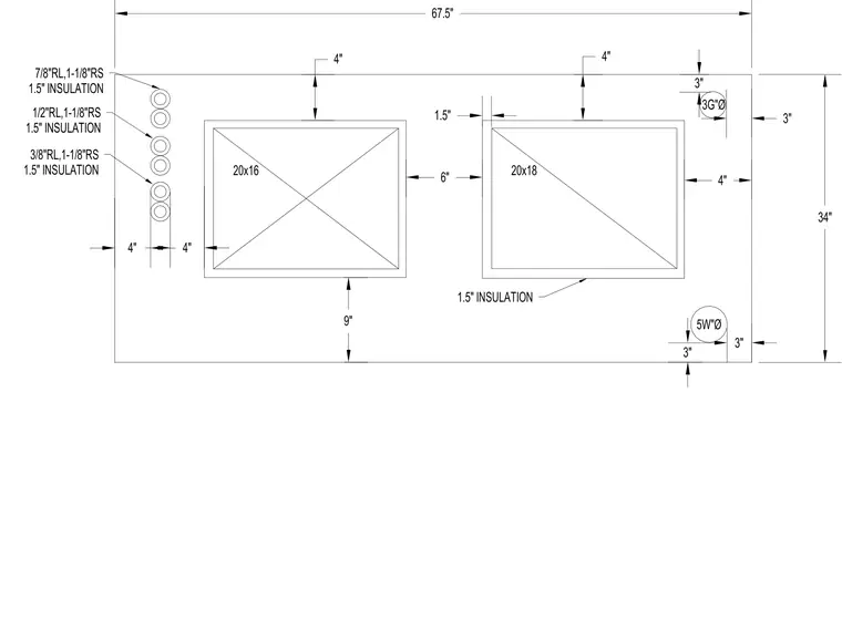
This diagram details the layout and dimensions for a dedicated outdoor air system shaft, measuring 67.5 inches wide by 34 inches high. It incorporates two rectangular duct openings sized 20x16 inches and 20x18 inches surrounded by 1.5-inch insulation. Circular penetrations include a 3-inch diameter opening and a 5-inch diameter opening positioned near the edges. Pipe configurations feature 7/8-inch, 1/2-inch, and 3/8-inch lines with 1-1/8-inch rigid support clearances and 1.5-inch insulation layers. Clearances and edge distances are dimensioned throughout to coordinate mechanical services within the shaft.
4" 4" 6" 1.5" 20x16 20x18 9" 3" 3G"Ø 3" 3" 3" 5W"Ø 4" 7/8"RL,1-1/8"RS 1.5" INSULATION 1/2"RL,1-1/8"RS 1.5" INSULATION 3/8"RL,1-1/8"RS 1.5" INSULATION 4" 4" 34" 67.5" 1.5" INSULATION
Members view this detail in full resolution, download the CAD files (SVG, PDF), and can adapt it in the built-in CAD editor — export DXF, DWG, or PDF.
Start membership