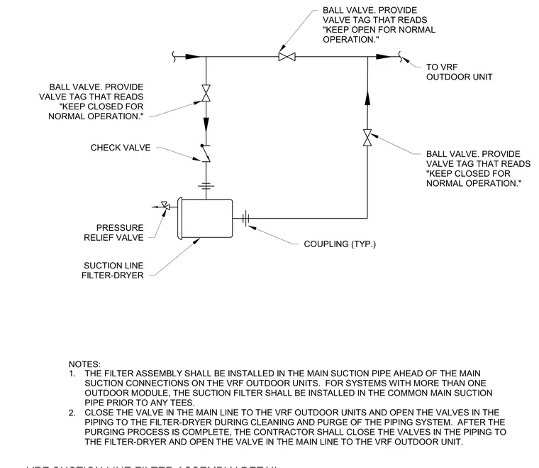
The suction line filter-dryer is installed in the main suction pipe ahead of the main suction connections on the variable refrigerant flow outdoor units. For systems with more than one outdoor module, the suction filter is installed in the common main suction pipe prior to any tees. The bypass piping utilizes ball valves and a check valve to isolate the filter-dryer during system cleaning and purging. A pressure relief valve is connected to the filter unit. Valve tags are provided to instruct operators to keep specific valves open or closed for normal operation.
NOTES: 1. THE FILTER ASSEMBLY SHALL BE INSTALLED IN THE MAIN SUCTION PIPE AHEAD OF THE MAIN SUCTION CONNECTIONS ON THE VRF OUTDOOR UNITS. FOR SYSTEMS WITH MORE THAN ONE OUTDOOR MODULE, THE SUCTION FILTER SHALL BE INSTALLED IN THE COMMON MAIN SUCTION PIPE PRIOR TO ANY TEES. CLOSE THE VALVE IN THE MAIN LINE TO THE VRF OUTDOOR UNITS AND OPEN THE VALVES IN THE PIPING TO THE FILTER-DRYER DURING CLEANING AND PURGE OF THE PIPING SYSTEM. AFTER THE PURGING PROCESS IS COMPLETE, THE CONTRACTOR SHALL CLOSE THE VALVES IN THE PIPING TO THE FILTER-DRYER AND OPEN THE VALVE IN THE MAIN LINE TO THE VRF OUTDOOR UNIT. BALL VALVE. PROVIDE VALVE TAG THAT READS "KEEP OPEN FOR NORMAL OPERATION." TO VRF OUTDOOR UNIT CHECK VALVE BALL VALVE. PROVIDE VALVE TAG THAT READS "KEEP CLOSED FOR NORMAL OPERATION." BALL VALVE. PROVIDE VALVE TAG THAT READS "KEEP CLOSED FOR NORMAL OPERATION." SUCTION LINE FILTER-DRYER PRESSURE RELIEF VALVE COUPLING (TYP.) 2.
Members view this detail in full resolution, download the CAD files (SVG, PDF), and can adapt it in the built-in CAD editor — export DXF, DWG, or PDF.
Start membership