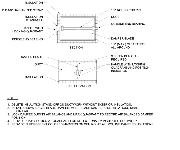
A single-blade rectangular manual volume damper is installed within a sheet metal duct surrounded by exterior insulation. The assembly features a damper blade mounted on a half-inch round rod pin supported by inside and outside end bearings. A handle with a locking quadrant and position indicator mounts to the side, utilizing a one-inch by one-eighth-inch galvanized strap and an insulation stand-off when exterior insulation is present. A half-inch maximum clearance is maintained all around the blade, and the blade is stiffened as required. Installation notes require deleting the insulation stand-off on uninsulated ductwork, providing a hat section at the quadrant for externally insulated ducts, locking the damper during air balance, and placing fluorescent colored markers on the ceiling at all volume damper locations.
SECTION SIDE ELEVATION NOTES: 1" X 1/8" GALVANIZED STRAP 1/2" ROUND ROD PIN DUCT OUTSIDE END BEARING DAMPER BLADE 1/2" (MAX.) CLEARANCE ALL AROUND INSULATION INSULATION STAND-OFF HANDLE WITH LOCKING QUADRANT INSIDE END BEARING INSULATION DAMPER BLADE STIFFEN BLADE AS REQUIRED HANDLE WITH LOCKING QUADRANT AND POSITION INDICATOR DUCT 1. DELETE INSULATION STAND-OFF ON DUCTWORK WITHOUT EXTERIOR INSULATION. 2. DETAIL SHOWS SINGLE BLADE DAMPER. MULTI-BLADE DAMPERS INSTALLATIONS SHALL BE SIMILAR. 3. LOCK DAMPER DURING AIR BALANCE AND MARK QUADRANT TO RECORD AIR BALANCED DAMPER POSITION. 4. PROVIDE "HAT" SECTION AT QUADRANT FOR ALL EXTERNALLY INSULATED DUCTWORK. 5. PROVIDE FLUORESCENT COLORED MARKERS ON CEILING AT ALL VOLUME DAMPERS LOCATIONS.
Members view this detail in full resolution, download the CAD files (SVG, PDF), and can adapt it in the built-in CAD editor — export DXF, DWG, or PDF.
Start membership