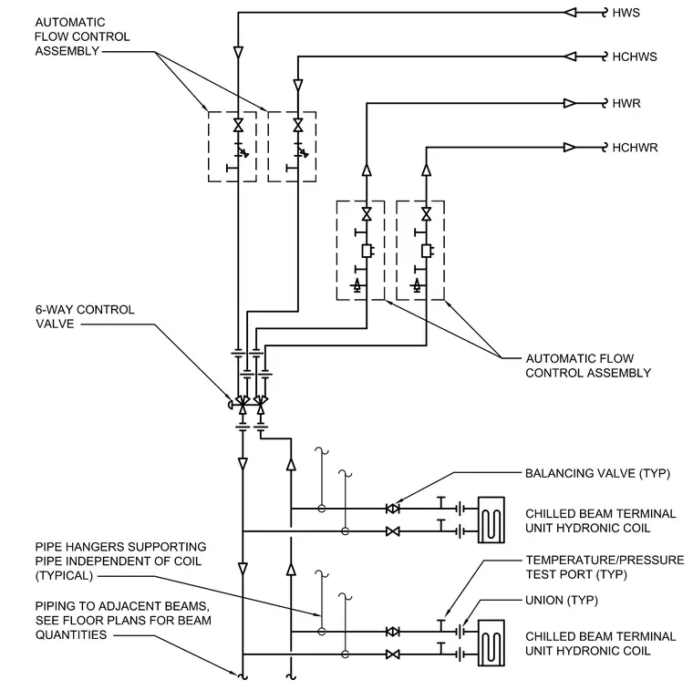
This piping diagram details the hydronic connections for chilled beam terminal units using a central 6-way control valve and automatic flow control assemblies. Hot water supply, hot water return, chilled water supply, and chilled water return mains tie into the valve arrangement. Unions and temperature/pressure test ports are provided at standard intervals for maintenance and diagnostics. Balancing valves are located on branches feeding the chilled beam terminal unit hydronic coils. Pipe hangers support the piping independently of the coils, and extensions route to adjacent beams per floor plans.
BALANCING VALVE (TYP) CHILLED BEAM TERMINAL UNIT HYDRONIC COIL CHILLED BEAM TERMINAL UNIT HYDRONIC COIL PIPE HANGERS SUPPORTING PIPE INDEPENDENT OF COIL (TYPICAL) UNION (TYP) TEMPERATURE/PRESSURE TEST PORT (TYP) AUTOMATIC FLOW CONTROL ASSEMBLY HWS HCHWS HWR HCHWR AUTOMATIC FLOW CONTROL ASSEMBLY 6-WAY CONTROL VALVE PIPING TO ADJACENT BEAMS, SEE FLOOR PLANS FOR BEAM QUANTITIES
Members view this detail in full resolution, download the CAD files (SVG, PDF), and can adapt it in the built-in CAD editor — export DXF, DWG, or PDF.
Start membership