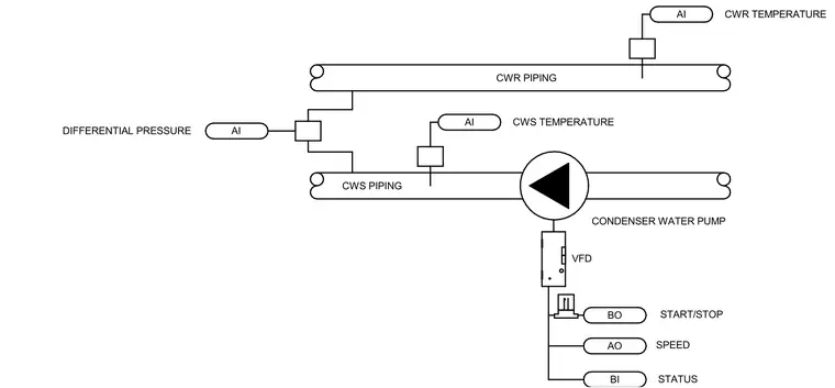
This control diagram outlines the instrumentation and control points for a condenser water pump operating within a mechanical piping system. The condenser water supply piping and condenser water return piping feature analog input temperature sensors monitoring both supply and return water temperatures, along with a differential pressure sensor connected across the lines. The pump motor is controlled through a variable frequency drive receiving a binary output start-stop signal, an analog output speed command, and a binary input status feedback. This schematic establishes the required automation points for pump operation and system monitoring.
BO AO BI VFD CONDENSER WATER PUMP START/STOP SPEED STATUS AI CWS TEMPERATURE AI CWR TEMPERATURE AI DIFFERENTIAL PRESSURE CWR PIPING CWS PIPING
Members view this detail in full resolution, download the CAD files (SVG, PDF), and can adapt it in the built-in CAD editor — export DXF, DWG, or PDF.
Start membership