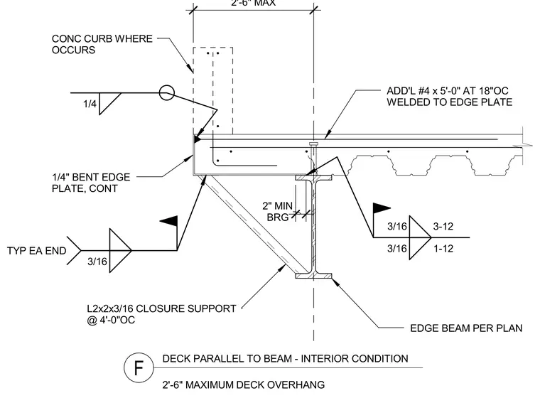
The assembly features a concrete filled metal deck running parallel to an edge beam per plan, with a maximum deck overhang of two feet six inches. A continuous one-quarter-inch bent edge plate forms the perimeter face, welded with a one-quarter-inch fillet weld and reinforced with additional number four bars measuring five feet zero inches at eighteen inches on center welded to the edge plate. An L2x2x3/16 closure support angle is spaced at four feet zero inches on center with a three-sixteenths-inch weld typically at each end. The metal deck bears on the edge beam with a two-inch minimum bearing requirement, secured with three-sixteenths-inch welds at one-twelve and three-twelve spacings. A concrete curb occurs at the perimeter edge where indicated.
3/16 TYP EA END EDGE BEAM PER PLAN 3/16 1)12 3/16 3)12 DECK PARALLEL TO BEAM ) INTERIOR CONDITION F 2')6" MAXIMUM DECK OVERHANG BRG 2" MIN L2x2x3/16 CLOSURE SUPPORT @ 4')0"OC CONC CURB WHERE OCCURS 1/4" BENT EDGE PLATE, CONT 2')6" MAX ADD'L #4 x 5')0" AT 18"OC WELDED TO EDGE PLATE 1/4
Members view this detail in full resolution, download the CAD files (SVG, PDF), and can adapt it in the built-in CAD editor — export DXF, DWG, or PDF.
Start membership