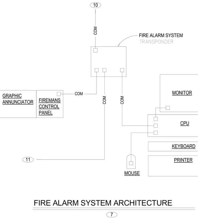
This schematic diagram outlines the overall architecture of a fire alarm system, mapping out communication pathways between core components. The central processing unit connects directly to a monitor, keyboard, printer, mouse, and a fire alarm system transponder via communication links. The transponder interfaces with a fireman's control panel and a graphic annunciator, establishing signal routing across the network. Labeled communication lines and numbered nodes coordinate the integration of each hardware unit within the building automation framework.
CPU MONITOR 10 COM COM COM MOUSE COM PANEL CONTROL FIREMANS 11 7 ANNUNCIATOR GRAPHIC FIRE ALARM SYSTEM PRINTER TRANSPONDER FIRE ALARM SYSTEM ARCHITECTURE KEYBOARD
Members view this detail in full resolution, download the CAD files (SVG, PDF), and can adapt it in the built-in CAD editor — export DXF, DWG, or PDF.
Start membership