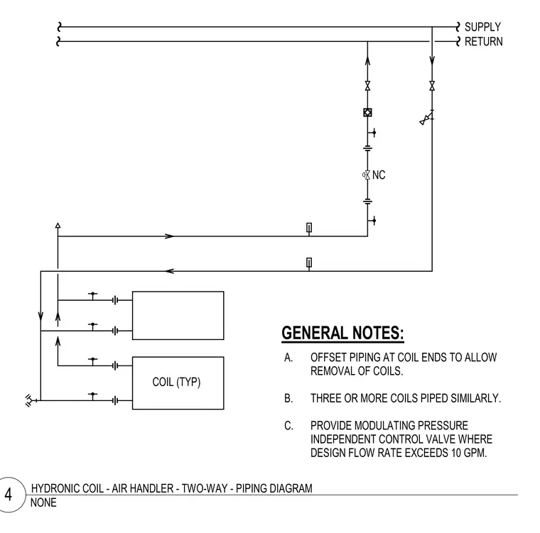
This piping schematic details a two-way control valve arrangement for typical hydronic coils connected to air handler units. Supply and return mains feed multiple coils piped in a similar configuration with offset piping at coil ends to allow for future removal. A modulating pressure independent control valve is specified for designs where the flow rate exceeds ten gallons per minute. Unions and isolation valves are provided at each coil connection for maintenance access.
SUPPLY RETURN COIL (TYP) A. OFFSET PIPING AT COIL ENDS TO ALLOW REMOVAL OF COILS. B. THREE OR MORE COILS PIPED SIMILARLY. C. PROVIDE MODULATING PRESSURE INDEPENDENT CONTROL VALVE WHERE DESIGN FLOW RATE EXCEEDS 10 GPM. GENERAL NOTES: NC NONE 4 HYDRONIC COIL - AIR HANDLER - TWO-WAY - PIPING DIAGRAM
Members view this detail in full resolution, download the CAD files (SVG, PDF), and can adapt it in the built-in CAD editor — export DXF, DWG, or PDF.
Start membership