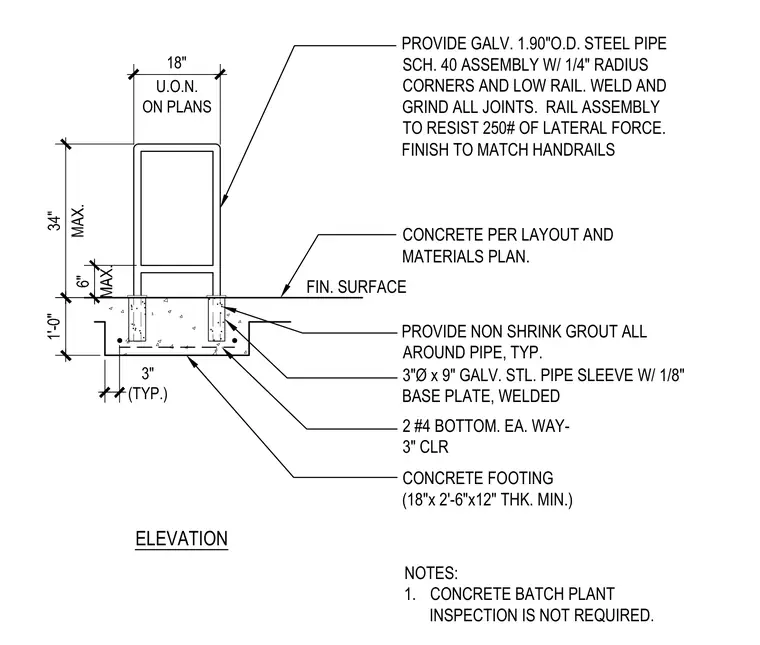
The assembly features a galvanized 1.90-inch outside diameter schedule 40 steel pipe rail with a low rail and one-quarter-inch radius corners, set into a three-inch diameter by nine-inch deep galvanized steel pipe sleeve with a welded one-eighth-inch base plate. Non-shrink grout is placed all around the pipe inside the sleeve, which is embedded in a concrete footing measuring eighteen inches by two feet six inches by twelve inches thick minimum. The concrete footing is reinforced with number four bottom bars each way with three inches of clearance. The rail stands at a maximum height of thirty-four inches with a six-inch maximum low rail and is designed to resist two hundred fifty pounds of lateral force.
ELEVATION 1'-0" CONCRETE PER LAYOUT AND MATERIALS PLAN. PROVIDE GALV. 1.90"O.D. STEEL PIPE SCH. 40 ASSEMBLY W/ 1/4" RADIUS CORNERS AND LOW RAIL. WELD AND GRIND ALL JOINTS. RAIL ASSEMBLY TO RESIST 250# OF LATERAL FORCE. FINISH TO MATCH HANDRAILS 6" MAX. FIN. SURFACE 3"Ø x 9" GALV. STL. PIPE SLEEVE W/ 1/8" BASE PLATE, WELDED PROVIDE NON SHRINK GROUT ALL AROUND PIPE, TYP. CONCRETE FOOTING (18"x 2'-6"x12" THK. MIN.) 3" (TYP.) 18" U.O.N. ON PLANS 34" MAX. 2 #4 BOTTOM. EA. WAY- 3" CLR NOTES: 1. CONCRETE BATCH PLANT INSPECTION IS NOT REQUIRED.
Members view this detail in full resolution, download the CAD files (SVG, PDF), and can adapt it in the built-in CAD editor — export DXF, DWG, or PDF.
Start membership