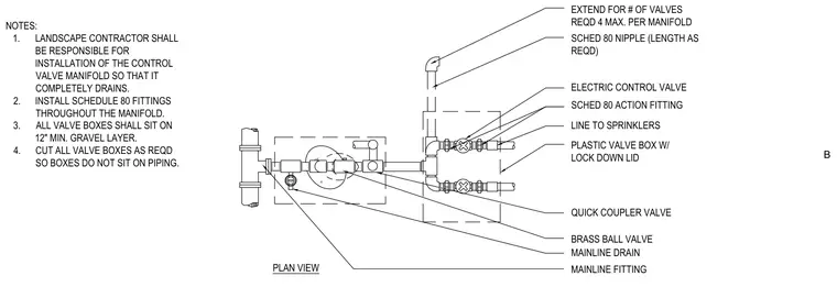
This plan view details an irrigation control valve manifold featuring a mainline connection, a brass ball valve, a quick coupler valve, and a mainline drain. Schedule 80 fittings and nipples are used throughout the assembly to accommodate up to four electric control valves per manifold. The entire configuration is housed within plastic valve boxes equipped with lock-down lids, which rest on a twelve-inch minimum gravel layer and are cut to prevent direct contact with the piping. The landscape contractor must ensure the installation of the manifold allows for complete drainage.
B NOTES: 1. LANDSCAPE CONTRACTOR SHALL BE RESPONSIBLE FOR INSTALLATION OF THE CONTROL VALVE MANIFOLD SO THAT IT COMPLETELY DRAINS. 2. INSTALL SCHEDULE 80 FITTINGS THROUGHOUT THE MANIFOLD. 3. ALL VALVE BOXES SHALL SIT ON 12" MIN. GRAVEL LAYER. 4. CUT ALL VALVE BOXES AS REQD SO BOXES DO NOT SIT ON PIPING. PLAN VIEW EXTEND FOR # OF VALVES REQD 4 MAX. PER MANIFOLD SCHED 80 NIPPLE (LENGTH AS REQD) MAINLINE FITTING ELECTRIC CONTROL VALVE SCHED 80 ACTION FITTING PLASTIC VALVE BOX W/ LOCK DOWN LID LINE TO SPRINKLERS QUICK COUPLER VALVE BRASS BALL VALVE MAINLINE DRAIN
Members view this detail in full resolution, download the CAD files (SVG, PDF), and can adapt it in the built-in CAD editor — export DXF, DWG, or PDF.
Start membership